On this page
I'd been typing on the same Anne Pro 2 for about five years, with the same keycaps and switches the whole time. I wasn't deep into the keyboard hobby. But building one from scratch was on my checklist.
I was hesitant at first. I watched a lot of videos, read some blogs and references, and then got a little ambitious and went for a split wireless keyboard. I'd done a bit of soldering before, when I modded my Anne Pro 2 to make it hot-swappable, meaning you can pull the switches out and swap them without desoldering anything. That was fun. I also burned my hand. With that much experience behind me, I pulled the trigger.
This isn't a full build guide. It's the important stuff and how it went. The full parts list is at the end.
Getting started
My first order was the 3D-printed case, the hot-swap sockets, enameled copper wire and the microcontroller.
For the case, Ryan has a site, ryanis.cool/dactyl, where you design the keyboard by adjusting things like the curve, the height and the number of keys, then download the STL file (the 3D model). You can send that STL file off to be 3D printed. I went with an aggressive 30-degree tent, which means each half tilts up toward the middle, like a roof.
How it works
The microcontroller is the brain of the keyboard. It's a small board that the USB cable plugs into, with contact points (pins) along its edges. None of this happens automatically, though. You decide what the board does, and you do that by writing the logic yourself: what should happen when two points touch, what should happen when they're released, and what counts as a keypress. A microcontroller doesn't know it's inside a keyboard. With the right wiring, code and a few extra parts like sensors and motors, you could build almost anything with one, like a drone, a home appliance or a small robot. A keyboard is one of the simplest things to start with, because it doesn't need any of those extras, just switches and wires.
For a keyboard, the idea is this: connect two of those pins with a wire and the microcontroller treats it as a keypress. Using the pin layout below, connecting P0.24 to P1.15 could register as A, and P0.24 to P1.13 as B, if that's how you've configured it. You could make them Z and X instead. The configuration part comes later.
You can use any of the programmable pins in the P0.* or P1.* groups. Check the pin layout for the exact board you buy. Mine was a nice!nano v2 clone, and its layout was close to the original but not identical. "Close enough" is not a pin-mapping strategy.
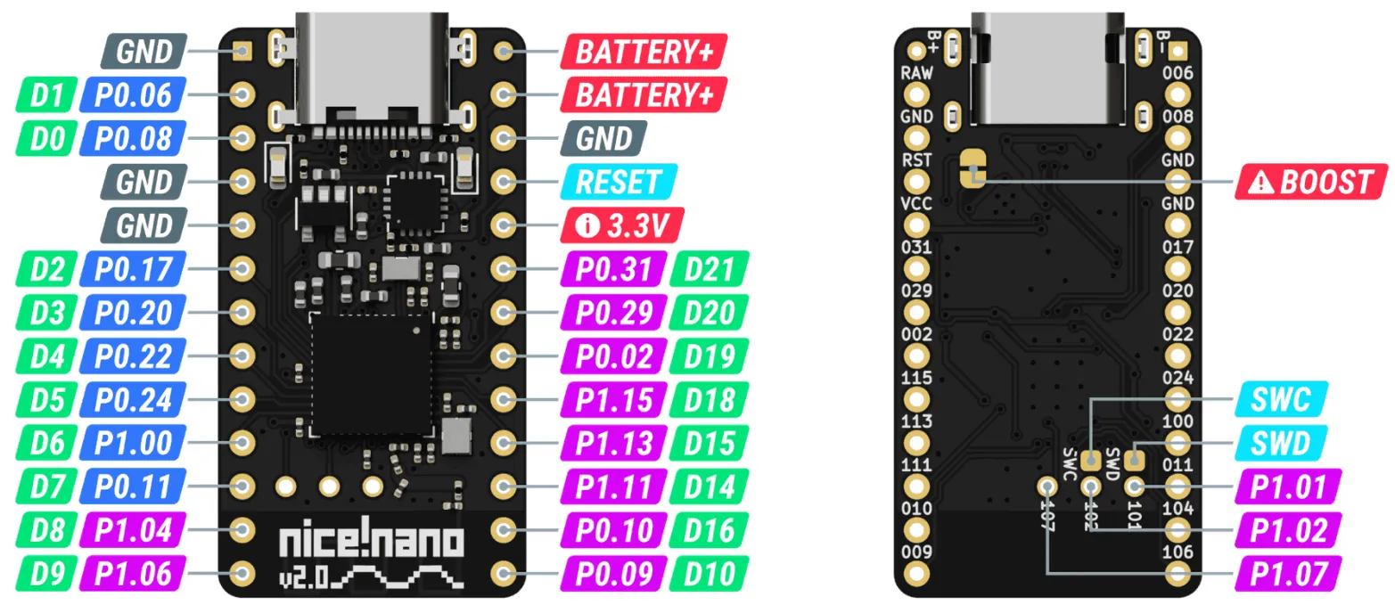
The keys are wired in a matrix, which is a grid of rows and columns. Each switch sits where a row and a column cross. A switch is a small part under each keycap that works like a gap in a wire: when you press the key, it closes the gap and connects its two contacts, and when you let go, it opens again. Here, pressing a switch connects its row to its column. The nice!nano scans the grid to work out which key was pressed, and the firmware maps that position to a key.
A 5 × 5 grid has 25 crossings, so it can hold up to 25 keys per half, and it only needs 10 pins. Giving every key its own pin would take 23 or more.
Mine is a 4x5 Dactyl Manuform. In its standard layout that's 23 keys per half: three full rows of 5, 2 keys on the bottom row and 6 thumb keys. I wired each half as a 5 × 5 grid, which leaves 2 of the 25 crossings with no key on them.
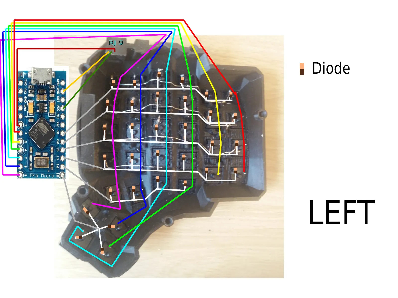
Every switch also needs a diode. A diode only lets current flow in one direction. Without them, pressing certain key combinations can create extra electrical paths through the grid, and the keyboard registers keys you never pressed. That's called ghosting. A diode on each switch blocks those paths, so several keys pressed together all read correctly.
Putting it together
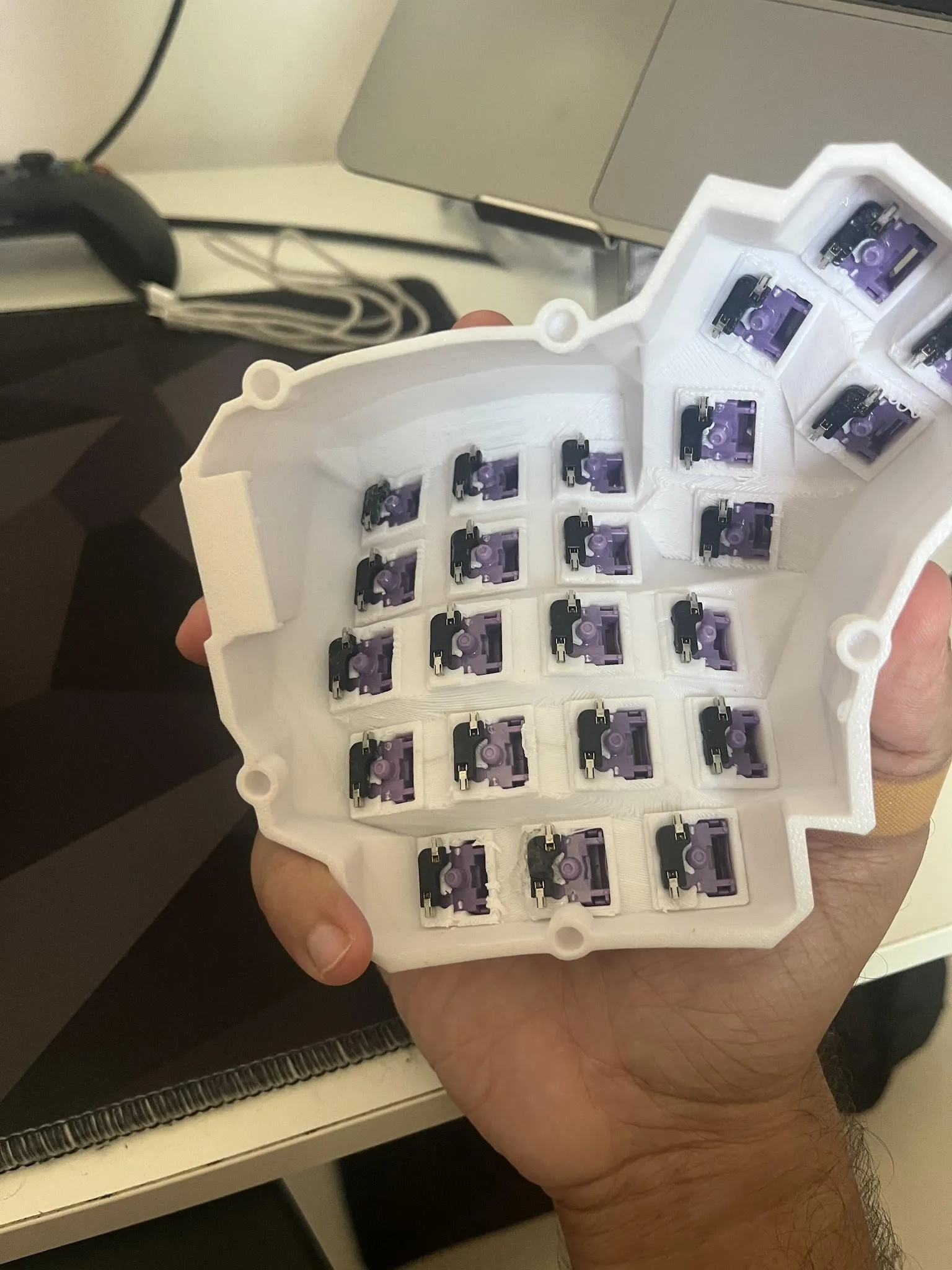
Since I was using hot-swap sockets, I wired the rows and columns to the sockets instead of the switches. First I glued the sockets into the 3D print with Fevikwik (superglue). I slotted some of them in wrong. Some I glued in backwards and had to pry back out. It was a mess. Plan everything before you glue anything down. Superglue is much more confident about your decisions than you should be.
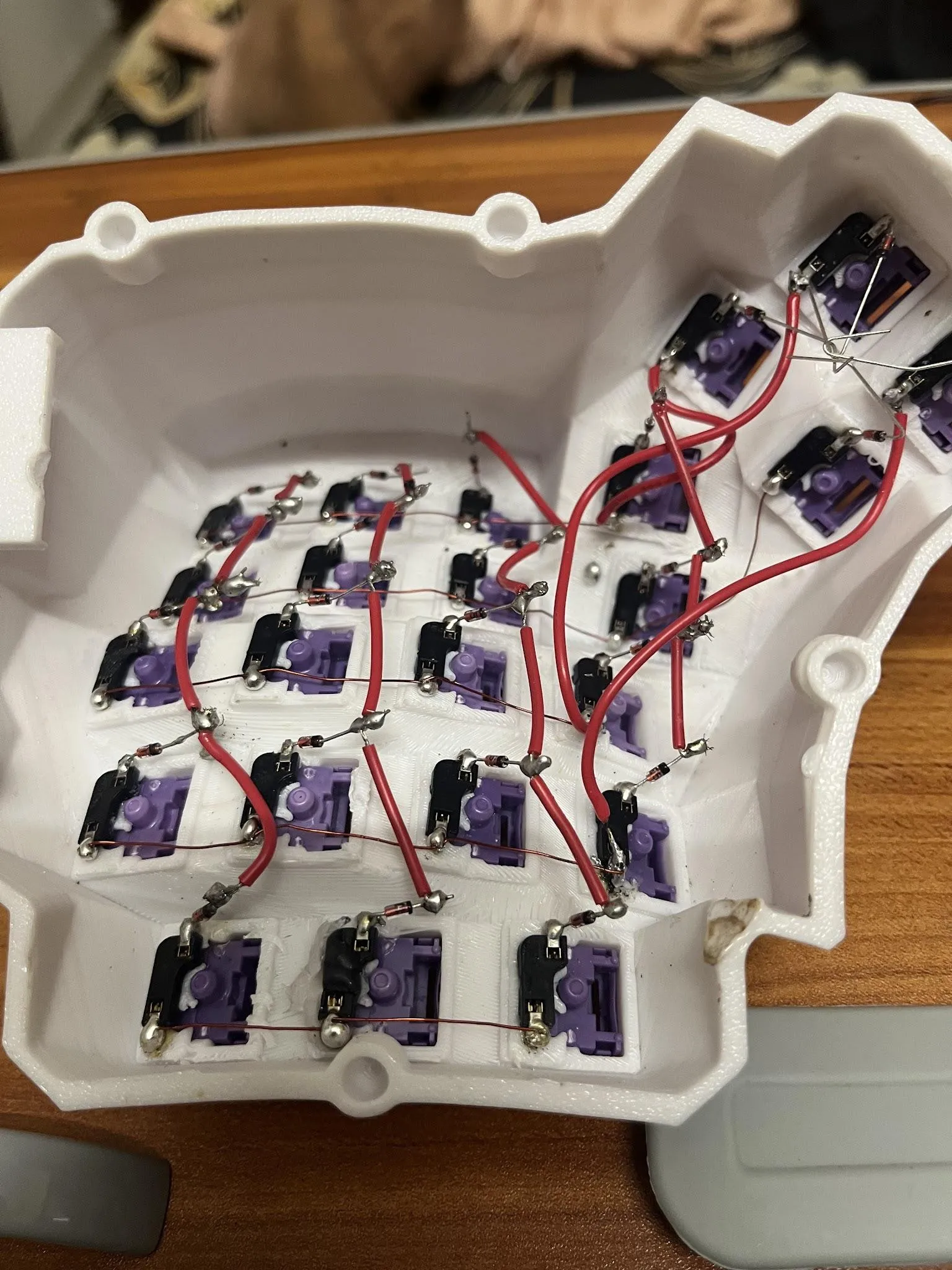
Then came the soldering. I used enameled copper wire for the connections, and I didn't know it has a thin insulating coating. I found out after I'd finished, when I tested the connections with a multimeter (a meter that, among other things, tells you whether two points are connected) and some of the circuits weren't complete. The wire looked connected, but electrically it was still wearing a tiny invisible raincoat. That one was on me. You have to burn or scrape the coating off where you make a connection. Solder onto a coated part and the connection just doesn't work. Some coatings, like the polyester one on mine, don't burn off at normal soldering temperatures, so scraping or sanding is more reliable. I redid some of them, connecting the wire at the cut ends where the copper was exposed.
The enameled wire was harder to work with, so I only used it for the columns, which don't have diodes. For the rows, which connect through the diodes, I used normal wire. Once everything was connected I checked every circuit with the multimeter again. Even with all that, it was one of the fun bits.
Next, the 5 rows and 5 columns go to the microcontroller. Before that you solder pin headers onto it (rows of metal pins that wires can plug onto), which is another fun part.
Boards like this have a reset pin. Shorting it to ground twice puts the board into a mode where you can install firmware. I wired those two pins to a tactile switch (a small push button), so I can just press it twice. You'll need this to install the ZMK firmware.
Then the battery. One pin is for positive and one is for ground. Use jumper cables here too, in case you want to swap the battery later. I put a switch on the positive wire so I can turn the keyboard on and off.
To mount everything in the case, I hot-glued around the USB sockets, the reset switch and the power switch. The battery and microcontroller are stuck down with double-sided tape, since hot glue isn't secure enough for them. The Fevikwik was only for the hot-swap sockets.
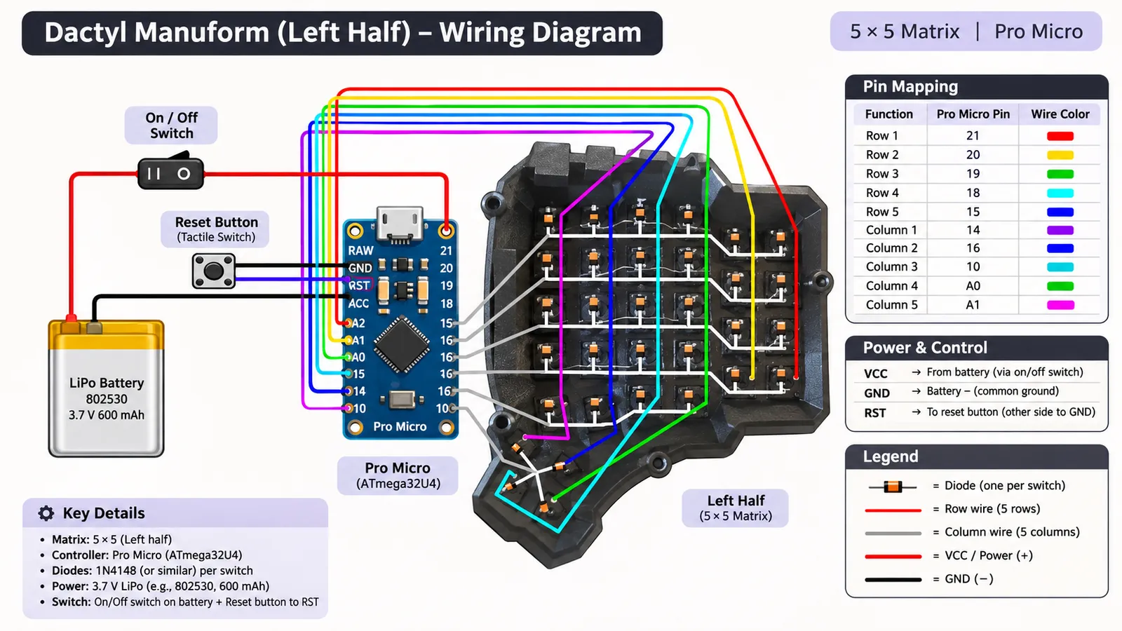
The diagram below shows how I wired the battery and the reset button. I had it drawn with AI, and the board in it is a Pro Micro, not a nice!nano, so its pin layout is completely different from mine. Use it to see how things connect, not which pins to use. The battery's positive wire runs through the power switch to the board's battery pin, its negative wire goes to ground, and the reset button sits between the reset pin and ground. Check your own board's pinout to find those pins.
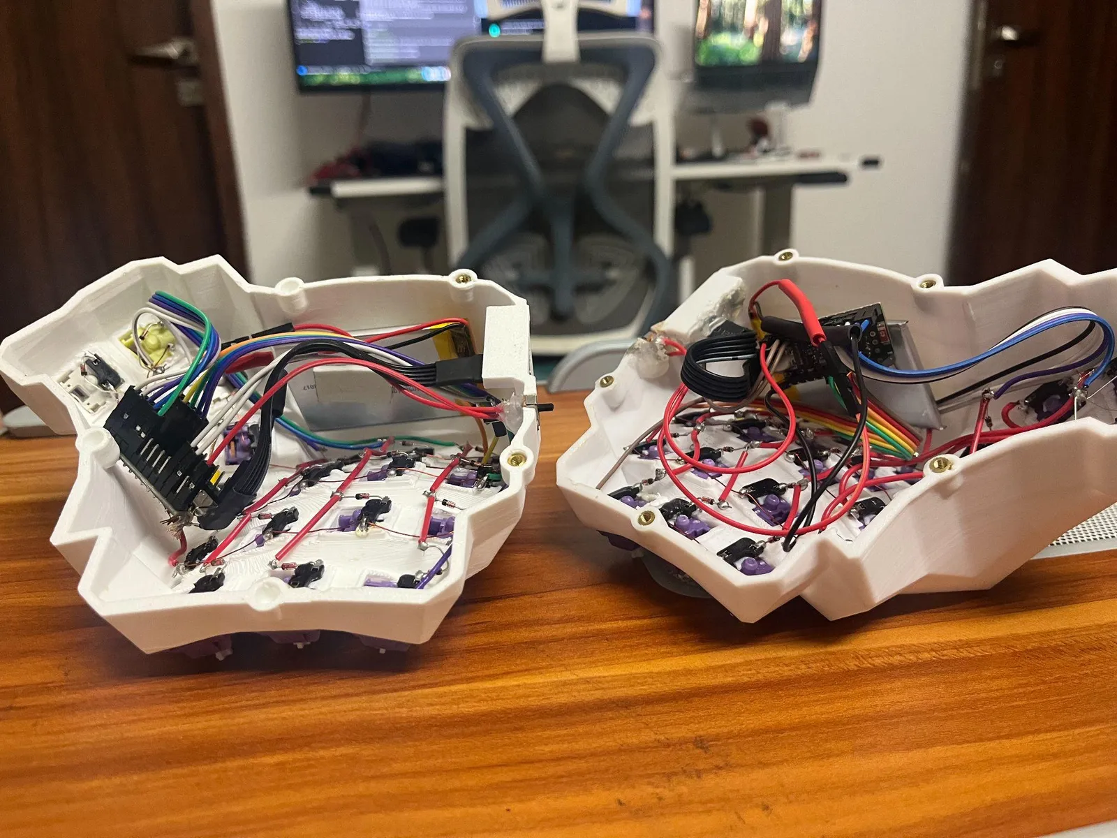
Once the left half is done, do the right half the same way, but keep in mind that it's a mirror image of the left. The sockets, the wiring and where everything sits in the case are all flipped. Don't copy the left half's layout exactly. Mirror it, and keep track of which column is which, because you'll need that later when you map the pins in the firmware.
The last hardware step is the screw inserts. They're heat-set, so you heat up the soldering iron and push each insert into its slot in the print. It melts the plastic around itself and sets there, ready for the screws later.
Firmware
Firmware is the software that runs on the microcontroller and decides what each key does. I used ZMK, because QMK (the other big option) can't officially run on the nice!nano due to licensing issues with Nordic's Bluetooth stack. The ZMK user setup guide has a CLI that clones the repo so you can start on your keymap.
There are two parts of that repo you need to understand yourself, because they depend on your hardware and how you want to customize it. A coding AI (like Claude or Cursor) can easily handle the rest of the setup.
- The
.dtsifile maps out your rows and columns, if they're the same on both halves. If the two halves use different pins, you specify those in an.overlayfile. - The
.keymapfile is where you set what each key does.
Logging for debugging is turned on and off in config/dactyl_manuform.conf.
My config is at github.com/riyaz942/zmk-dactyl. I'm using home row mods, where the home row keys act as modifiers like Shift or Ctrl when you hold them down. So far it's going well.
One nice thing about ZMK is that you don't have to build anything locally. You push your changes and the CI/CD pipeline builds the firmware for you. You download two UF2 files (the firmware files), one for each half, plus a settings_reset file you only need if the halves stop pairing.
To install one, connect the microcontroller to your computer over USB and double-press the reset button. The board goes into bootloader mode and shows up as a drive. Drag the UF2 file onto that drive. It installs and exits on its own. Unplug it, plug it back in and press some keys to check it works.
That only works for testing the left half. In ZMK one half is the central, which talks to the computer, and the other is the peripheral, which sends its keypresses to the central over Bluetooth (BLE). My left half is the central. To test the right half, you connect the left half and turn on the right half's battery.
The right half wouldn't talk
With both halves flashed, you turn the keyboard on with the battery switch and connect it to your computer over Bluetooth. If you've enabled a passkey in your config, you'll be asked for one.
For me, the left half worked. The right half only registered keypresses (in the logs) when I plugged it straight into my laptop over USB. It wasn't talking to the left half at all.
For quite a while I was sure my config was wrong. I tried a lot of variations: making the right half the central and the left the peripheral, turning on several experimental modes, and so on. No luck. The two halves just wouldn't talk to each other.
So I turned on debug logging. On the central, everything looked fine, including it listening for the peripheral. On the right half, keypresses were fine too, but it errored out every time it tried to connect to the central. My conclusion was that the right microcontroller's Bluetooth didn't work. Apparently that happens with clone nRF52 boards. I didn't know that going in.
I couldn't return or exchange it, because I'd soldered the pin headers on, and the seller's terms say they don't accept soldered microcontrollers. So I ordered a new one, and with it some debugging gear: a breadboard (a board you plug parts and wires into without soldering), a few buttons and some wires for testing. I'd never used a breadboard, so that was new.
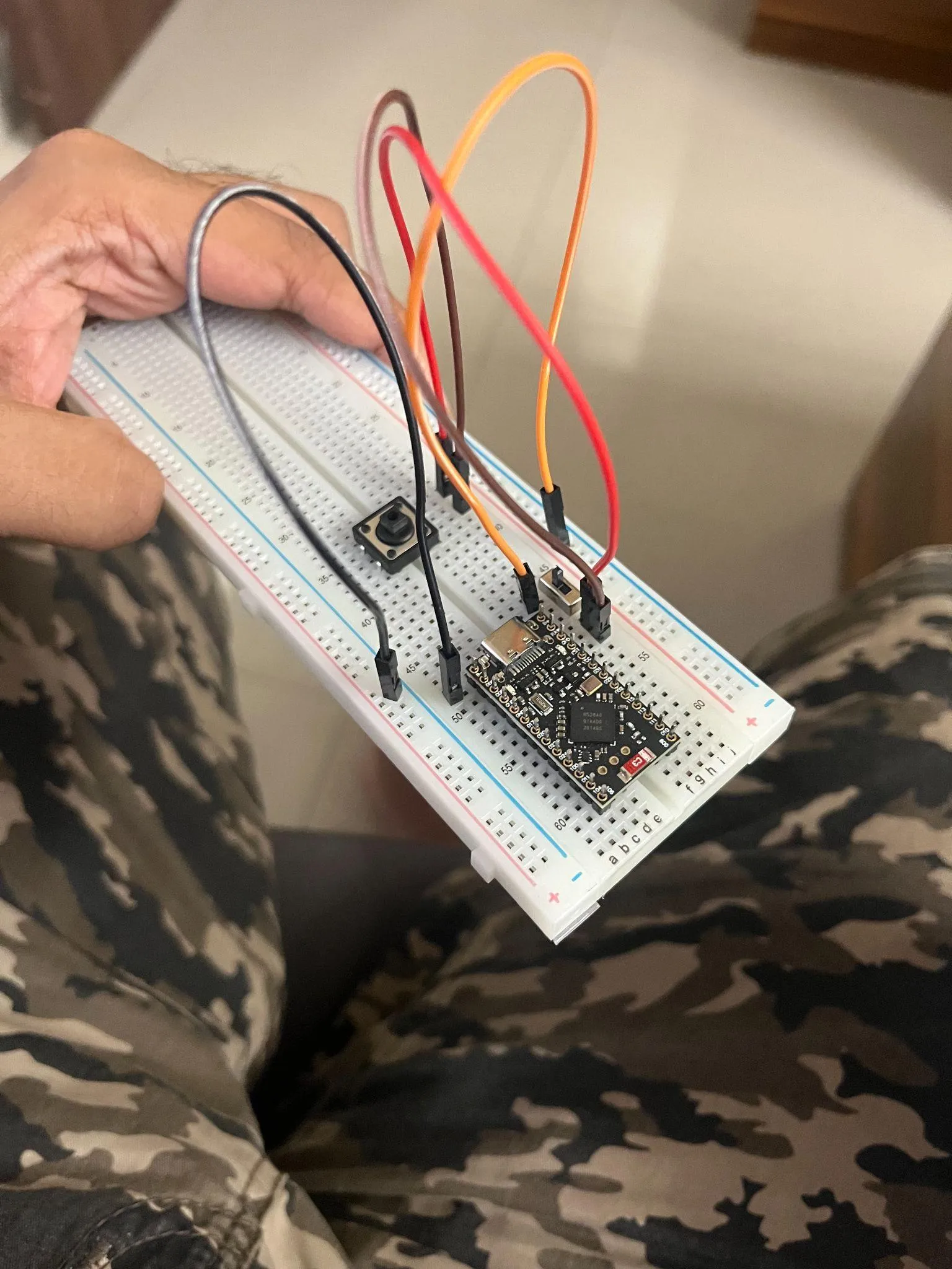
When the new board arrived, I installed the right-half UF2 file straight onto it and checked the logs. It connected to the left half. Bluetooth worked.
Then I tested the pins one by one, shorting two at a time and checking whether the keystroke registered. Without pin headers in place, it's awkward to touch a wire or the multimeter to two of the board's pin holes at once. So I put the pin headers into the breadboard, connected the board to them, and used wires to connect its pins. I could have managed without the breadboard, but it made this easier. I think it'll be worth it for future projects too.
I also went over the wiring with the multimeter, touching both ends of each row and column to make sure the connection went all the way through.
Some of the pins I'd wired the right half to didn't work. Clone board, again. Since I'd learned my lesson and hadn't soldered it this time, I could have replaced it. But I didn't want to wait again, so I worked out which pins were dead, moved those jumper wires to working pins, and updated the pin config in ZMK to match. Then I checked everything again. Thankfully, it all works now.
Only after all that testing did I solder the pin headers onto the new board. Since everything was wired with jumper cables, it was easy to plug it all in and get going.
Painting it
Once it worked, I experimented with some timings and config and was quite happy with it. That left the looks. I'd ordered the case in white on purpose so I could paint it.
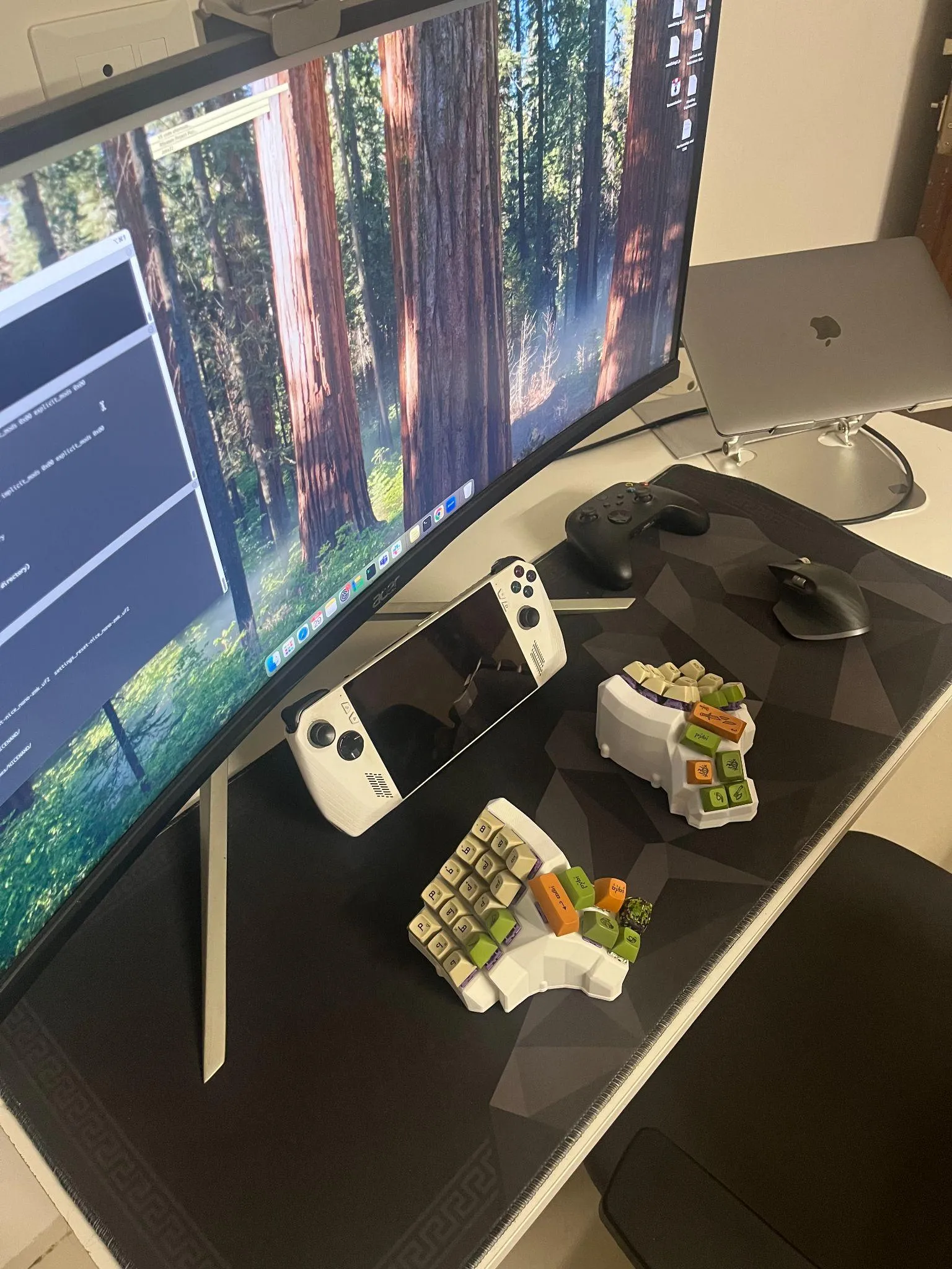
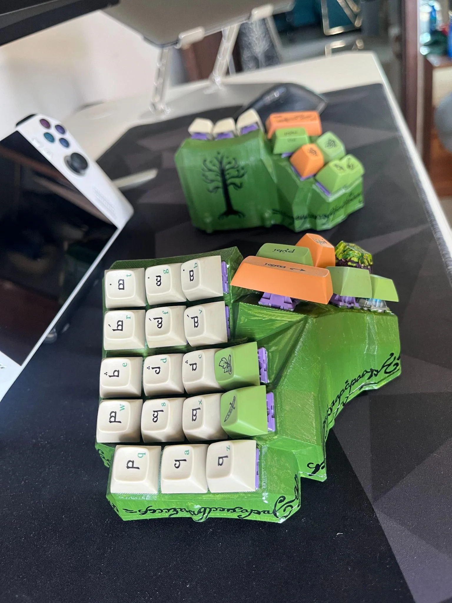
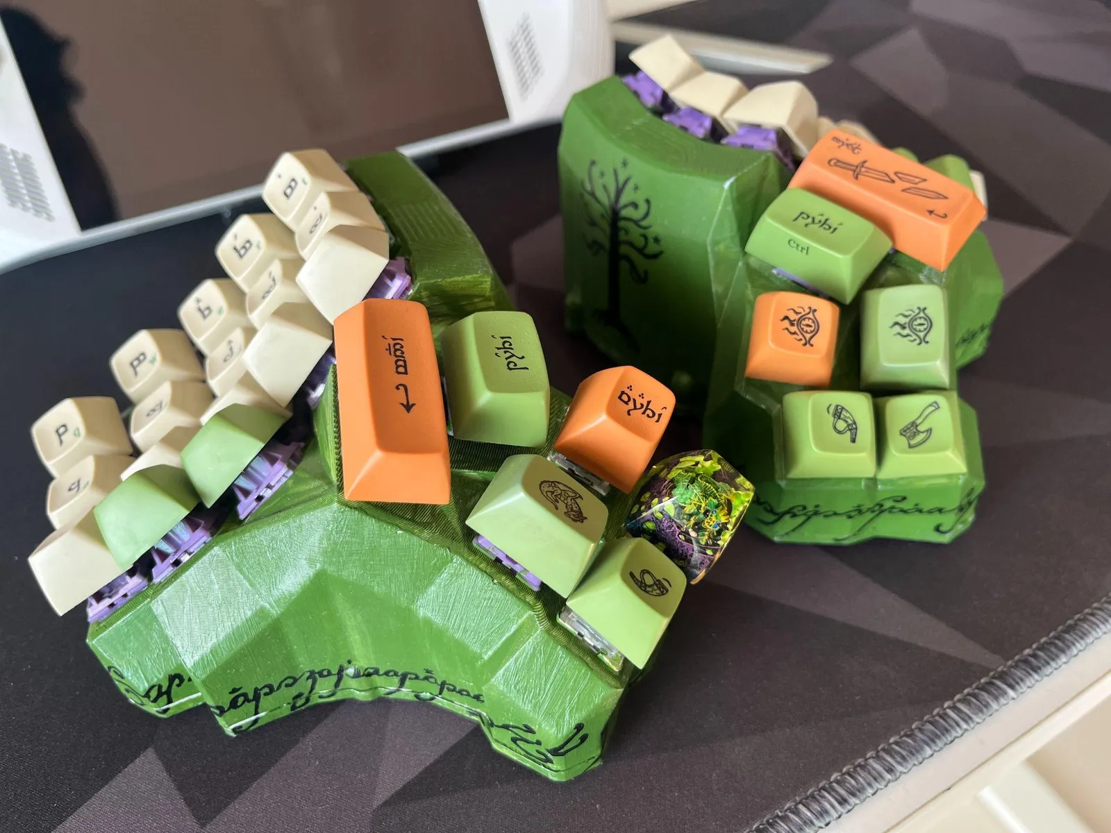
I already had a Lord of the Rings theme going with Elvish keycaps, so I asked my wife to paint the case green and draw Lord of the Rings references on it.
Here's how it turned out.
A year later
I'm writing this about a year after the build, so I may have missed some details and some of the resources I used for inspiration or reference.
I usually tinker with software. This was my first hardware project, and I loved it: the soldering, the debugging, and building something physical instead of software. I might take on a few more.
Typing on it was slow for the first week or so. My fingers had to learn a new geography. After a week or two I was back to the speed I had on a normal keyboard. The 30-degree tent means I don't have to twist my arms to type. Each arm rests comfortably on a chair armrest, and I can put the halves wherever I want.
The one nuisance is layers. One extra layer would be fine, but this board has three on top of the letters: one for navigation, one for numbers and symbols, and one for Bluetooth and other settings. The numbers I know well by now. The symbols are harder. Commas, colons, quotes and the like are something I just have to memorize, and if I haven't used one in a while, I forget where it lives. If I build another one, I'll add a few more keys so those symbols and the arrows get their own spots.
Using it with one hand is harder. To reach everything with one hand I'd need layer keys on each half, and with this few keys that's tricky. But I don't usually type with one hand, so I've just gotten used to it.
When I built this, AI coding tools were just taking off, and I was typing on it a lot. These days most of what I write is prompts and messages, and I mostly dictate those with voice-to-text. I still use the keyboard when I'm in a meeting and doing something on the side, or when I just want to listen to music and work. Then I type. It may not get the hours it once did, but at least it isn't sitting in a drawer wondering what it did wrong.
Even so, building it was a lot of fun. There's the cool factor, and it's an awesome feeling to use something I built myself.
Key takeaways
- Wire the matrix to the microcontroller with jumper cables. When a pin or a whole board turns out dead, you move a wire instead of desoldering.
- Enameled wire is coated. Burn or scrape the coating off where you solder, and check every circuit with a multimeter.
- Clone nRF52840 boards can have dead Bluetooth or dead pins. Test a new board before you solder pin headers onto it.
- Plan the socket layout before you glue anything down.
- With ZMK, CI builds the firmware for you. The parts you need to understand yourself are the
.dtsi/.overlaypin mapping and the.keymap. The rest is a good job for a coding AI.
Parts list
Most of the parts came from robu.in, which seemed to have everything I needed. I already had a soldering kit with the iron, solder, a desoldering pump and wire cutters. The switches and keycaps came from my old keyboard, so they're not listed.
| Part | Notes |
|---|---|
| 3D-printed case | 3ding.in, 1700 INR to print one side |
| Hot-swap sockets (CPG151101S11) | |
| nice!nano v2 clone | The microcontroller, one per half |
| Diodes | One per switch |
| Enameled copper wire | For the columns |
| Male-to-male jumper wires | |
| Female-to-female jumper wires | |
| Male-to-female jumper wires | |
| Tactile buttons | Reset button |
| Slide switches | Power switch |
| Batteries | |
| Heat-set screw inserts | |
| Screws | |
| Glue gun | |
| Desoldering wick | For cleaning up mistakes |
| Multimeter | For debugging |
| MB102 830-point solderless breadboard | For debugging |
| LEDs | Bought for "debugging" and never used |